


When a node is selected
When a [Node] is selected from a [Group] in the [Object configuration] palette, the following items can be set.
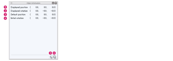
(1) Displayed position
The [X coordinate], [Y coordinate] and [Z coordinate] can be set for the position of the [Node]. Enter a numeric value to move the [Node]. This is not applicable for the [Root node folder].
(2) Displayed rotation
Set the angle of a [Node] with [Rotate around x axis], [Rotate around y axis] and [Rotate around z axis]. Enter a numeric value to change the angle of the [Node] based on its origin. This is not applicable for the [Root node folder].
(3) Default position
The [X coordinate], [Y coordinate] and [Z coordinate] can be set for the position of the origin of the [Node]. Enter a numeric value to move the origin of the [Node]. This is not applicable for the [Root node folder].
(4) Initial rotation
[Rotate around x axis], [Rotate around y axis] and [Rotate around z axis] can be set for the angle of the origin of the [Node]. Enter a numeric value to change the angle of the origin of the [Node]. This is not applicable for the [Root node folder].
(5) Adjust origin position
Clicking this displays the [Adjust origin position] dialog box. The origin position of the node can be adjusted by selecting it in the [Object configuration] palette.
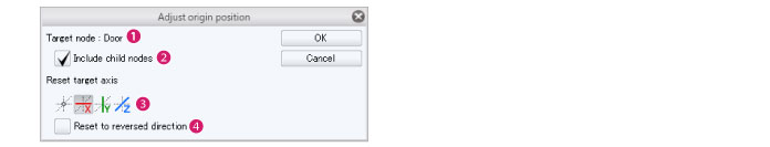
Adjust origin position dialog box
|
(1) Target node |
Displays the name of the [Nodes] for adjusting the position of origin. |
|
(2) Apply to Child node(s) |
When checked, the origin is adjusted for all nodes included in the [Node] folder. |
|
(3) Reset target axis |
Resets the default axis for the origin’s position. Select [Center], [x axis], [y axis] or [ z axis]. When [Center] is selected, the node’s origin is reset to its center. When either the [x axis], [y axis], or [z axis] are selected, the selected axis is reset to face forward. The origin’s value can be confirmed via [Default center] in the [Object information] palette. |
|
(4) Reset to reversed orientation |
This can be set when [x axis], [y axis] or [z axis] are selected as [Standard direction]. When checked, the origin’s position is reset to the opposite direction of the direction selected for [Reset target axis]. The origin’s value can be confirmed via [Default center] in the [Object information] palette. |
(6) Recalculate normals
Clicking these displays the [Recalculate normals] dialog box. This recalculates the normals for the nodes selected in the [Object configuration] palette.
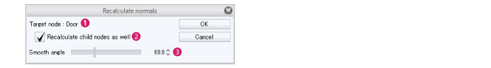
Recalculate normals dialog box
|
(1) Target node |
Displays the name of the [Nodes] for adjusting the position of origin. |
|
(2) Apply to Child node(s) |
When checked, the normals are recalculated for all nodes included in the [Nodes] folder. |
|
(3) Smooth angle |
If the angle between the faces is larger than the angle set here, the normals are calculated to not be continuous. |
|
|
For information on how to display normals, see "Document Window" . |