


Setting Movability Parts
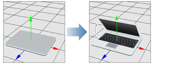
Record movement or rotation of the [Nodes] (parts) of 3D objects so that they can be operated by moving the [Nodes] in CLIP STUDIO PAINT.
Add a [Movability] part to the [Object configuration] palette and record the movement of the [Nodes] of the 3D object.
1Add a movability part
Create a [Movability] part in the [Object configuration] palette.
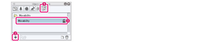
(1) Select [Movability] from the group on the [Object configuration] palette.
(2) Click [Add new].
(3) The [Movability] part is added.
2Record the movement of the node
Select a [Node] in the [Object information] palette and record the movement.
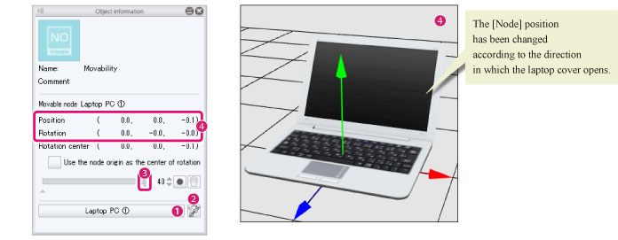
(1) Select the [Node] to be moved from [Target node].
(2) Click [Turn this node into a movable node ] to confirm a [Target node ].
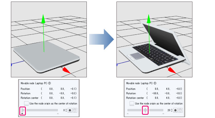
(3) Move the slider to the right end.
(4) Input the [Position] and [Rotation] values to adjust the position of the [Node]. The results of the adjustment can be checked in the [Document] window.
|
|
·If it is difficult to move the [Node], you can select the [Move parts] sub tool and edit it using the manipulators in the [Document] window. For details, see "Move parts" . ·To change and check the camera angle of the [Document] window, see "Setting Camera Angles" . ·In case the value for the [Rotation center] was changed, and a value for [Rotation] is set, the [Node] rotates according to the position set for the [Rotation center]. In addition, when selecting the [Move part origin point] sub tool, the position of the “rotation center” moves accordingly. For details, see "Move part origin point" . ·Checking [Use the node origin as the center of rotation] and setting a value for [Rotation] the node is rotated with its origin at the center. The origin of the [node] can be edited by operating the manipulator in the [Document] window through the [Move part origin point] sub tool. For details, see "Move part origin point" . |
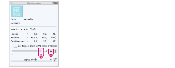
(5) Click [Add key frame].
(6) The [Node] position is recorded in the slider and a [Key frame] (▲) is added below the slider.
3Playing movability parts
Drag the slider in the [Object information] palette left and right.
The [Node] in the [Document] window moves with the slider.
If you are satisfied with the result, the setting process is now complete.
In the top picture, the laptop cover is down. If there are any movement issues like this, proceed to the next step.
4Adjust the movement of the part
In the [Object information] palette, create an additional key frame and adjust the movement of the [Node].
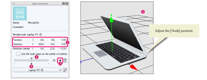
(1) Drag the slider to the position where the movement of the [Node] is odd.
(2) Input the [Position] and [Rotation] values to adjust the [Node] to its natural position. The results of the adjustment can be checked in the [Document] window.
(3) Click [Add key frame].
(4) The [Node] position is recorded in the slider and the [Key frame] is added below the slider.
(5) Repeat steps 3-4 if necessary until the movement becomes natural.